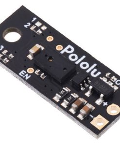


This small lidar-based distance sensor reports the distance of objects up to about 50 cm (20″) away with a pulsed signal similar to a hobby servo control signal. A digital microcontroller pin can be used to time the length of each high pulse, which encodes the measured distance. The sensor works over an input voltage range of 3.0 V to 5.5 V, and the 0.1″ pin spacing makes it easy to use with standard solderless breadboards and 0.1″ perfboards.
Note: The maximum range of 50 cm is only achievable for high-reflectance objects in good ambient conditions. Lower-reflectivity targets or poor ambient conditions will reduce the maximum range.
Overview
This compact sensor makes it possible to measure the distance of objects up to about 50 cm (20″) away using a simple digital pulse width interface (similar to a hobby servo control signal). It uses a short-range lidar module to precisely measure how long it takes for emitted pulses of infrared, eye-safe laser light to reach the nearest object and be reflected back, allowing for 3 mm resolution. As long as the sensor is enabled, it takes continuous distance measurements and encodes the ranges as the widths of high pulses, which can then be timed by a microcontroller using a single digital input.
 |
 |
|
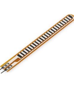
A camera with no IR filter shows the infrared light emitted by a Pololu Digital Distance Sensor. |
|---|
The relationship between measured distance d (in mm) and pulse width t (in µs) is as follows:
Please note that while this sensor can detect objects almost all the way up to the sensor face, the effective minimum distance it can measure is around 1 cm, so objects closer than 1 cm might still result in a measured distance of around 1 cm. Three connections are necessary to use this module: VIN, GND, and OUT. These pins are accessible through a row of 0.1″-pitch through holes, which work with standard 0.1″ (2.54 mm) male headers and 0.1″ female headers. The VIN pin should be connected to a 3 V to 5.5 V source, and GND should be connected to 0 volts. The sensor outputs its digital pulses on the OUT pin. The low level of the pulses is 0 V, and the high level is VIN. A red LED on the back side of the board also lights whenever an object is detected (the closer the object, the brighter the LED). The board has an optional ENABLE pin that can be driven low to put it into a low-power state that consumes approximately 0.4 mA. This pin can be accessed through a via or its neighboring surface-mount pad on the back side labeled “EN” on the silkscreen. The ENABLE pin is pulled up to VIN, enabling the sensor by default. The board features four surface-mount configuration jumpers that determine its operation mode. Different versions of the Pololu Digital Distance sensors ship with the appropriate jumpers pre-populated with 0 Ω resistors. These resistors can be desoldered from the populated spots or solder bridges can be added across the unpopulated spots to convert one sensor version into another. The table in the section below shows the jumper settings for the different versions. The board has one mounting hole intended for use with #2 or M2 screws. We have several different versions of Pololu Digital Distance Sensors, all with the same dimensions and pinout: These are the output graphs for the three digital output versions that just report if an object is in their detection range: The output graph is a bit different for the version that uses a pulse width to encode the measured distance (item #2668). The output for this version is similar to hobby servo control signals and is shown below as a function of time: Specifications

Using the sensor


The Pololu Digital Distance Sensor family
Output type
Sensor
Maximum
rangeMinimum
update
rateJumper
settings
(4321)
digital
(does not provide
distance measurement)Digital output, 5cm
5 cm
145 Hz
0000
Digital output, 10cm
10 cm
115 Hz
0010
Digital output, 15cm
15 cm
95 Hz
0100
pulse width
(provides distance
measurement)Pulse width output, 50cm max
50 cm
50 Hz
1110


Dimensions
Size:
0.85″ × 0.35″ × 0.122″
Weight:
0.4 g
General specifications
Maximum range:
5 cm
Sampling rate:
145 Hz1
Minimum operating voltage:
3.0 V
Maximum operating voltage:
5.5 V
Supply current:
30 mA2
Output type:
digital3
Identifying markings
PCB dev codes:
irs16a
Other PCB markings:
0J13085
Notes:
Fast Shipping & Professional Packing
We offer a broad range of shipping options owing to our long-running partnerships with UPS, FedEx and DHL. Our warehouse personnel are expertly trained and will wrap your items according to our exact and precise specifications. Your products will be subjected to an exhaustive examination before they will be properly packaged prior to being delivered. Everyday, we send to thousands of clients in multiple countries. This shows our commitment to be the largest online retailer in the world. We have distribution centers as well as warehouses in Europe as well as the USA.
Note: Orders that contain more than one product will be assigned a distinct processing time dependent on the particular item.
We will inspect each and every one of the products before they are shipped. The majority of orders are shipped within 48 hours. The delivery time will be between 3-7 working days.
Returns
The inventory is always changing, and not fully managed by us because of the involvement of many parties including the factory and our warehouse. The stock can change at any moment. Please be aware that it's possible for your order to be out of stock after you have made the order.
Our policy is valid for a period of 30 days. If 30 days have passed in the past since you purchased and we are unable to offer you a return or exchange.
To be eligible for a refund, your product must be unopened and in the same condition as you received it in. It must also be returned in its original packaging.
Related products


Sensor
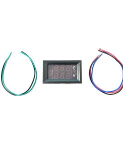
0.28″ DC 0-100V 50A Panel Meter Dual Digital Voltmeter and Ammeter (Red + Blue) Canada Robotix